


The solution for complex sound-reinforcement challenges and permanent installations.
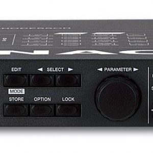
The DFC is a digital 3-way mono controller designed to be used in an HK AUDIO amplifier rack.
With its specially developed software and matching MIDI interface, it offers a comprehensive
means of managing a complex sound reinforcement system via an intuitive analog-style interface.
PA Remote Management
The distributed sound systems used at today?s large venues have become so complex over the
years that they now practically require a full-blown control center just to set up and manage them
efficiently and maintain a clear overview over them. To ensure that each individual acoustic area is
treated by a dedicated part of the PA, the various sections of the overall system must be divided into
sensible groups,such as PA wing left/right, center cluster, long-throw, near-field, sub-low, delay 1,
delay 2, and so on.
Such a division usually leaves you with a large number of different sound coverage zones, which have
to be treated separately but managed centrally.
A system controlled in the traditional manner would normally need at least one EQ, delay, and crossover
channel per coverage zone. Add to that the necessary standard cabling and rack and truck space,
and you end up with a considerable number of racks and, what?s more, a complicated set up. The
Digital Field Controller offers an easier and more cost-effective solution. The word “controller” usually
refers to functions such as crossover and protective circuitry; the DFC expands the meaning of the word to
include a very different meaning: PA-REMOTE-MANAGEMENT.
To simplify the handling of large system configurations featuring several amplifier racks, you can network
up to 32 DFCs via MIDI interface, controlling them remotely with the aid of a PC.
Using the control program that was developed especially for this very application, you can manage even
extremely large PA systems very conveniently, accessing all installed DFCs individually, if you wish, equalizing
and correcting delay values for each single device separately.
At the same time, you can choose to group several DFCs together in order to control an entire group of
speakers (PA wing, delay tower, subs) that are powered by several amp racks as one. All settings that you
enter for a given group are automatically transmitted to the appropriate controllers. This option for example lets
you effortlessly implement a delay station: All you have to do is assign all of the DFCs that control the speakers
of the delay station to one group, and set one single delay value, which is then automatically transmitted to all
DFCs in that group.
This feature considerably reduces the amount of cables you have to connect and simplifies the entire signal-processing
operation considerably. The group control function lets you comfortably handle PA systems of any size,
from club gigs to major open-air festivals.
The extensive control functions of the DFC system can be operated from the graphic user interface of the
PC software as conveniently and intuitively as you are accustomed to with individual analog equipment.
The graphic user interface of the PC software makes using the extensive control functions of the DFC system
as intuitive as using familiar analog equipment. In fact, you can manage your entire system from just three
screens.
The first screen displays the status of the peak and temperature limiters in the three frequency bands of every
attached DFC. So, the operational status of the complete system can be checked easily from either the FOH
position or the control room.
You can also create groups, and the zones they are intended to cover, in this window.
By double-clicking on the Group, you arrive at a second screen. Here you can assign a name to the group (e.g.
“Long-throw Left“). Additionally you can set basic functions here, such as Mute, Level, Phase Reverse and Delay,
for every one of the three frequency bands, as well as for the Group Master.
From the third screen you can access, for each connected controller and for each created group, a 28-band equalizer
with 15dB of cut or boost, Set-Flat and Bypass functions, and gain control.
Dynamics
The dynamic range of the input section plays a crucial role in a digital audio controller because
* the greater the dynamics of the input section, the better the headroom.
* the greater the dynamic range, the lower the audible noise.
* dynamic reserves in the input stage are the basis of excellent dynamics at the output stage
Through the innovative use of Split-Stack Technology, in which two 20-bit AD converters are stacked together, the
DFC achieves a dynamic range of 117 dB at the input! That exceeds what a high-quality 24-bit converter can do by
4 dB!
Absolute Correction of Frequency and Phase
In contrast to standard digital controllers, the DFC does not use IIR (Infinite Impulse Response) filters that are adjustable
at the unit itself. Instead, at each output it uses one FIR (Finite Impulse Response) filter, which accomplishes both
the dividing and equalizing functions in one.
The difference between the two types of controllers is essentially how the signal is processed in the controller. Most
other digital controllers have a fixed number of filter components which allow you to implement a low-pass filter with a
slope of 12 decibels, or a fully parametric filter. The desired type of signal processing operation is made possible by
a combination of these components. The processed signal is routed to the device’s output.
For example, to separate the signal for a woofer with a slope of 48 dB, the device requires eight filter components (four
low and high-pass filters each). Optionally, you also can assign additional parametric filters to equalize the system.
The FIR filters of the DFC, on the other hand, work with a sample of the desired filter impulse response. The sample is
uploaded to the filter using Fourier transformation. It shapes the frequency and phase response of the filter. The sample
is downloaded via the same process. As a result, FIR filters can execute detailed equalization operations with extremely
steep slopes and freely assignable amounts and phases. This type of signal processing operation requires a PC. It
computes the required impulse response for the desired signal processing operation via an inverse Fourier transformation.
Once calculated, the filter can no longer be varied. If you want to change a parameter or value, the entire filter has to be
recomputed. On the other hand, you no longer have to execute a number of tasks manually. For example, you do not
have to adjust the delay and phase corrections for the split signals, since these operations are carried out automatically.
The DFC is not a universal controller, but is set up for a specific system and it knows its specific characteristics. This is
the only way a sound reinforcement system can really be equalized effectively.
Together with frequency response, the phase response of a system plays a very large role in how that loudspeaker
system reproduces sound. Phase errors are rooted in three main causes:
1. Each loudspeaker itself produces phase errors because different frequencies require different travel times
on the membrane.
2. Loudspeaker enclosures always function as high bandpass filters of the second order in the case of sealed
enclosures, and of the fourth order in the case of bass-reflex cabinets. All filters have the effect of making the
phase response less linear. This includes the filters of a passive crossover network.
3. In most systems, the voice coils of individual loudspeaker components are not lined up on one axis. As a
result, sound waves generated from these components are not in sync but out of phase, yielding distortion in
the phase response.
The DFC is the first controller which not only uses time alignment to compensate for any time lags between the
individual components, but goes a step further and compensates for the phase distortion arising from the enclosure,
the crossover networks and each individual loudspeaker.
So now, for the first time, a tool is available that uses a comprehensive approach for truly flattening the phase response
of an entire sound reinforcement system.
For the user this means a previously unattainable level of clarity and sonic purity, more effective use of equalization,
a more natural soundstage, and a greater tolerance among listeners for higher volume levels.
Biamped and 3-Way Active: Best of Both Worlds!
Both two-way and three-way systems have specific advantages and disadvantages. In combination with the two-way
systems of the HK AUDIO R-Series and T-Series, the Digital Field Controller enjoys all the typical benefits of both
two-way and three-way systems without having to suffer their disadvantages. As already mentioned, the DFC is dealing
virtually with three separate ways ? low, mid and high ? but recombines the mids and highs before the output stage.
In other words, the DFC produces a two-way signal, and yet each frequency band can be muted separately, and even
its phase can be reversed separately! In a mid/high loudspeaker module such as the RT 112 (12“+2“), you are free to
control the volume of the 12″ speaker separately, reverse its phase, or even mute it briefly altogether without affecting
the high frequency driver at all. And that, mind you, although both are connected to the same speaker cable and both
are running over one and the same passive crossover.
* Comprehensive frequency adjustments
* Quick access to speaker components
* Individual speakers can be muted
* Corresponds to traditional international usage
* Easier to wire up
* Less power amplifiers are required
* Less electrical power is needed
* Less weight
* Less warehouse / truck space needed
* Fewer sources of error
* Higher Return on Investment
Perfect Protection for the System: the Limiters of the DFC
The HK AUDIO Digital Field Controller includes two anticipatory limiter sections per frequency band:
a) Thermal Limiter
Since the DFC has data on the entire sound system, power amps included, it can continually monitor the operating
state of its individual components. Taking into consideration how long the system has been running, it compares the
processed signal with the stored maximum system values, and momentarily reduces the output as needed. In this
way, the PA is protected against the dangers of overload.
b) Peak Limiter
The signal which has been processed by the DFC is checked with a peak detector before it reaches the output. If the
signal is too high, the peak limiter section is directly activated; it calculates how much to reduce the signal before the
peak signal reaches the output stage. In contrast to previous analog and digital controllers, the DFC does not use a
feedback circuit of the sort where the limiter only reacts after the first peak has already gone through. Instead, the signal
between the peak detector and the limiter is delayed by two milliseconds, allowing the needed corrections to have
already been made before the peak reaches the outputs of the DFC and, therefore, the P.A.
Delay Functions
The DFC features both a master delay and a frequency-band delay. The master delay serves to compensate for the time
lag between individual coverage zones, for example between the FOH PA and delay towers farther back in the audience.
Up to 2000 milliseconds of delay is available to sync loudspeakers that are up to 680 meters (2230 feet) apart from each
other, and that should be enough for most applications…
The frequency-band delay offers up to 100 milliseconds to align the individual components of a PA stack with each other,
for example if the mid/high cabs are flown but the bass cabs are resting on the floor. Both types of delay can be entered
in time (milliseconds) or distance (feet or meters).


Reviews
There are no reviews yet.